






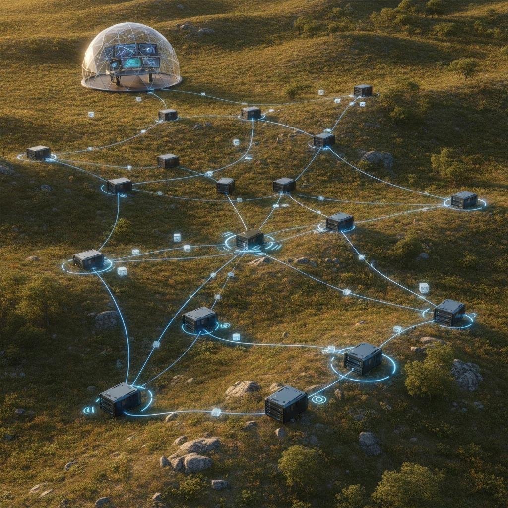
Field engineers deploying distributed radar systems often run into the same wall: individual transceiver nodes perform admirably in bench tests, but the moment a cluster of twenty or more nodes attempts to share synchronized track data across uneven or contested terrain, latency balloons and co-channel interference cripples throughput. When RF links saturate, the issue is rarely sensor hardware sensitivity; it is a structural failure of data distribution. Without deliberate network topology optimization, distributed arrays degrade into chaotic noise floors and single-point-of-failure backhauls.
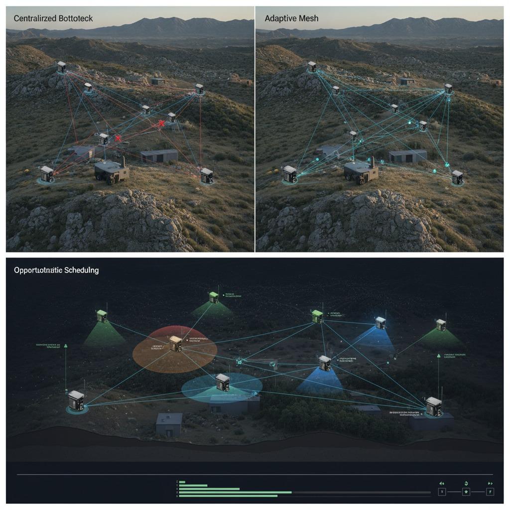
Whether you are designing perimeter defense installations, perimeter security for critical infrastructure, or counter-UAS arrays, moving from static routing to an adaptive network model determines whether targets are tracked continuously or lost in hand-off delays. This guide breaks down the architectural problems inherent in fixed distributed sensing and outlines practical approaches to configuring dynamic, resilient radar networks.
The Structural Bottleneck in Multi-Static Sensing
Historically, radar and high-bandwidth sensor deployments relied on centralized, hub-and-spoke models. Remote nodes capture raw returns or intermediate frequency (IF) data, beaming it back to a command node or central processing rack via point-to-point links. In benign environments with clear lines of sight, this architecture is straightforward to calculate and maintain.
In practice, physical clutter, mobile obstacles, and local electromagnetic jamming quickly degrade fixed links. If the central relay goes offline or experiences severe multipath fading, downstream nodes are cut off entirely. Even in systems transmitting processed target state vectors (rather than raw I/Q data), uncoordinated broadcasting results in packet collision, unpredictable queue delays, and blind spots. Solving this requires shifting computational logic from a rigid star topology to a dynamic structure that treats node links as temporary, fluid variables.
Four Pillars of an Adaptive Radar Network Architecture
Transitioning from a fragile sensor cluster to an adaptive array requires four complementary networking and scheduling mechanisms working in concert.
1. Ad-hoc radar network formation
Nodes cannot depend on pre-assigned routing tables when operating in non-line-of-sight conditions or when units are dropped into position rapidly. Implementing reliable ad-hoc radar network formation allows newly energized nodes to broadcast discovery beacons, evaluate neighbor signal-to-noise ratios (SNR), and negotiate clustering roles autonomously. Instead of demanding immediate full-bandwidth links to an upstream server, the network forms localized processing sub-graphs, selecting transient cluster heads based on signal clarity and compute availability.
2. Mesh radar connectivity
Point-to-point connections create clear systemic vulnerabilities. By layering mesh radar connectivity across the array, every node acts as an active relay for its adjacent peers. This allows target track data to route around topographic barriers, foliage attenuation, or local jamming without requiring elevated base station masts. The challenge here lies in managing the routing overhead: if the link-state broadcast consumes too much of the channel, sensor telemetry drops. Engineers should favor lightweight, distance-vector or proactive path-cost protocols tailored specifically for short, bursty sensor frames rather than heavy enterprise mesh solutions.
3. Opportunistic sensing scheduling
Continuous transmission invites detection, burns power, and generates self-interference across overlapping sectors. By integrating opportunistic sensing scheduling, the network adjusts both transmit pulse repetition frequencies (PRF) and cross-node reporting intervals based on threat probability and channel states. When an edge node identifies an ambiguous signature, adjacent nodes temporarily shift their duty cycles and spatial look-angles to provide cross-bearing confirmation. When sectors are quiescent, nodes throttle back emissions, freeing RF spectrum for administrative synchronization and background backhaul.
4. Self-healing sensing topology
Hardware failures, physical strikes, or battery depletion are realities in long-term remote sensing. An effective deployment relies on a self-healing sensing topology capable of detecting dropped heartbeats within milliseconds. When an intermediate relay node fails, adjacent sensors re-weight the graph edges, re-route telemetry through secondary mesh links, and re-allocate sensing sectors to cover the gap left by the defunct node. This prevents local dropouts from escalating into blind sectors across the wider tracking grid.
Comparing Topology Strategies for Distributed Arrays
Different operational profiles dictate distinct tradeoffs between synchronization precision, backhaul consumption, and installation complexity:
| Topology Model | Bandwidth Overhead | Resilience to Node Loss | Synchronization Complexity | Ideal Application |
|---|---|---|---|---|
| Star / Hub-and-Spoke | Low to Medium | Very Poor (Central node is critical) | Low (Central clock reference) | Permanent perimeter installations with clear fiber/cabled backhaul |
| Clustered Mesh | Moderate | High (Cluster heads fail over dynamically) | Moderate (Boundary clock distribution) | Medium-scale fixed sites with mixed line-of-sight and RF congestion |
| Fully Decentralized Ad-Hoc | High (Dynamic routing tables) | Exceptional (No single point of failure) | Very High (Distributed PTP/GPSDO required) | Rapid-deployment military arrays, autonomous vehicle swarms, contested zones |
Hardware Constraints and Practical Engineering Caveats
It is easy to sketch out self-reconfiguring node graphs in simulation software, but physical implementation demands strict attention to component-level limitations:
Clock drift kills multi-static coherence: If your topology design relies on nodes contributing to joint bistatic tracking or coherent fusion, microsecond-level timing offsets render data useless. While GPS-disciplined oscillators (GPSDO) are standard, environments prone to GNSS denial require high-stability oven-controlled crystal oscillators (OCXOs) or chip-scale atomic clocks (CSACs), alongside network-based precision time protocol (PTP/IEEE 1588) distribution built directly into the mesh routing layer.
Do not ship raw I/Q over wireless mesh: A common architectural mistake is designing dynamic RF mesh links with the expectation that uncompressed, wideband sensor returns can be sent downstream. Even optimized mesh radar connectivity struggles under the payload of raw radar frames. Edge processing—extracting target centroid, velocity, and radar cross-section (RCS) vectors locally—is mandatory. The network should transport synthesized tracks and metadata, reserving high-bandwidth bursts only for target confirmation.
Power envelopes dictate network agility: In remote setups using solar-assisted battery reserves, nodes that route too much third-party traffic will drain their power cells prematurely. Network routing metrics must incorporate remaining battery life as an edge weight; otherwise, a node sitting at a central geographic intersection may exhaust its energy within hours simply by acting as an unthrottled data relay.
Common Integration Mistakes
- Neglecting Co-Site Interference: Placing high-gain communications transceivers physically close to sensitive radar receiver front-ends without adequate cavity filtering or frequency separation. The mesh link ends up desensitizing the radar receiver.
- Over-Engineering Route Recalculation: Setting ad-hoc topology refresh intervals too low. If the routing protocol updates every few milliseconds, control frames will crowd out actual detection data, causing packet storms.
- Failing to Test Boundary Degradation: Testing the network only within tight clusters and failing to evaluate performance when edge nodes operate at marginal signal levels (e.g., -95 dBm packet receipt with significant frame drops).
Frequently Asked Questions
How does opportunistic sensing scheduling affect target tracking latency?
If an opportunistic scheme throttles update rates too aggressively during quiet states, initiating a lock on a fast-moving target (like a micro-UAS) may take slightly longer. To counter this, nodes should utilize adaptive kinematic thresholding: any low-confidence trigger instantly transitions the local cluster into a high-duty surveillance mode.
Can commercial Wi-Fi mesh hardware handle dynamic radar backhaul?
Generally, no. Commercial off-the-shelf (COTS) 802.11s mesh solutions introduce unpredictable jitter and prioritize throughput over strict deterministic delivery. Radar networks typically require customized MAC layers, TDMA-based polling, or dedicated software-defined radios (SDRs) operating in protected or specialized frequency bands.
What is the typical compute overhead of a self-healing sensing topology?
Running local routing engines, heartbeat monitors, and distributed scheduling algorithms usually consumes less than 5% of a modern embedded processor's capacity (such as an ARM Cortex-A or small FPGA SoC). The bulk of your compute budget will remain dedicated to digital signal processing (FFTs, CFAR, Doppler filtering).
Next Steps for Integration Teams
Before locking in your physical network design, map out the worst-case RF environment and conduct comprehensive link-budget calculations that account for both radar emissions and data link overhead. Focus your early integration cycles on validating edge-processing thresholds so that data transferred across the mesh is strictly limited to structured target vectors. If your deployment operates in contested or obstructed zones, prioritize field-testing ad-hoc routing protocols on bench radios to evaluate failover times and jitter before committing to broad hardware production.