





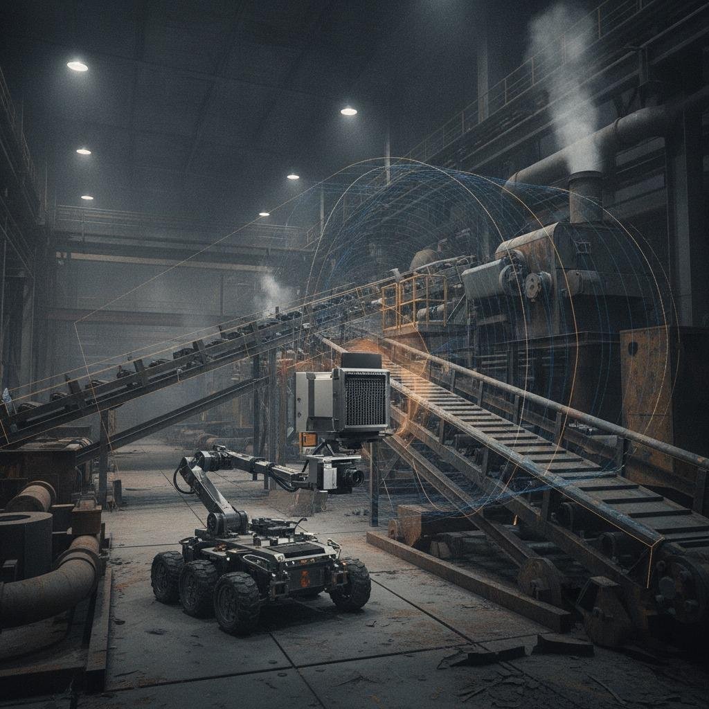
Industrial inspection engineers and spatial computing teams know exactly where traditional optical mapping falls apart. In gravel quarries, processing mills, subterranean utilities, and automated shipyards, airborne dust, steam, and variable illumination routinely blind standard camera rigs. Even state-of-the-art stereo and monocular photogrammetry pipelines drift when surface features disappear or lighting changes abruptly. While LiDAR provides solid metric coordinates, industrial LiDAR sensors remain expensive, fragile, and prone to severe beam scattering in heavy particulate atmospheres. This persistent operational bottleneck has driven teams toward texture mapping with radar depth—a sensor fusion approach that leverages millimeter-wave or 4D imaging radar to anchor dimensional geometry while wrapping high-resolution visual imagery over the resulting structural framework.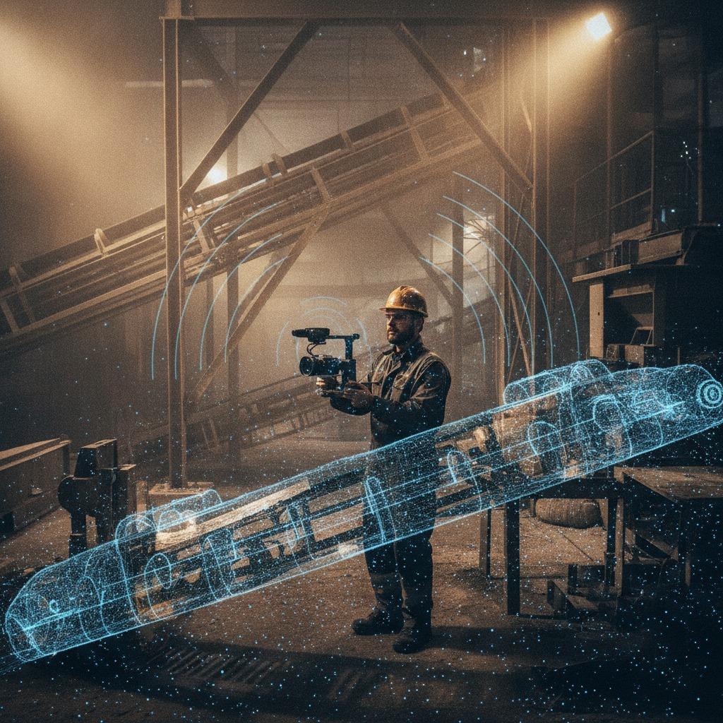
The premise is straightforward, but the physics can be punishing. Radar penetrates non-conductive airborne debris, fog, and grease with ease, yielding dependable range and velocity data regardless of ambient lighting. However, radar returns are inherently sparse, noisy, and subject to multipath scattering. Making visual texture stick to radar-derived geometry requires rethinking how spatial data is gathered, registered, and filtered before any pixel ever hits a polygon.
The Geometry-Texture Disconnect on the Factory Floor
Standard 3D imaging relies heavily on visual feature points. When an autonomous hauler enters a dust plume or an automated inspection crawler navigates a poorly lit ballast tank, optical feature tracking fails. The pipeline loses metric scale, leading to deformed wireframes and blurred texture projections.
Radar provides absolute radial distance and Doppler data that optical systems lack. However, the angular resolution of millimeter-wave radar (often operating at 77 GHz or 79 GHz) is orders of magnitude coarser than an optical camera's pixel grid. If you attempt direct back-projection—taking raw radar reflection points and stretching camera frames across them—the resulting visual model looks like a crumpled sheet. The engineering challenge is not simply acquiring data; it is constraining the visual pose estimation using radar range measurements so that the optical camera can texture-map a geometrically honest surface.
Core Architecture: Merging RF Returns with Visual Streams
Building dependable spatial models from heterogeneous sensors generally follows one of two implementation tracks:
1. Radar-Aided Digital Twin Construction
In long-term asset management, such as monitoring dockside cranes, structural trusses, or mining conveyors, radar-aided digital twin construction provides a durable baseline. The radar array handles global scale and structural boundary detection, ensuring that environmental variations across different seasons or shift hours do not introduce metric drift. Visual cameras then pass over these boundaries to project surface wear, corrosion patterns, and identification markers directly onto the surface planes. The radar guarantees that a steel column measured at three meters wide remains precisely three meters wide, regardless of how much steam or glare is present during a specific scan.
2. Radar-Based Structure from Motion (SfM)
When mapping dynamic or poorly mapped facilities from mobile platforms (such as AMRs or UAVs), standard visual odometry frequently slips on wet concrete or featureless sheet metal. Incorporating radar-based structure from motion introduces metric range constraints into the bundle adjustment solver. As the platform navigates, radar Doppler readings provide instantaneous ego-velocity, while persistent radar targets establish rigid spatial anchors. This keeps the camera's trajectory mathematically stable, allowing high-resolution frames to align correctly across adjacent surface patches without seams or parallax tearing.
Overcoming Sensor Disparities in Radar Photogrammetry Integration
Achieving clean radar photogrammetry integration requires engineering around several physical realities that pure software algorithms often ignore:
- Spatial Calibration Between Divergent Centers: A camera lens focuses light onto a CMOS plane with a well-defined optical center. A radar transceiver array radiates from multiple patch antennas, creating an effective phase center that can drift based on incidence angles. Rigid, cross-modal extrinsic calibration using corner reflectors paired with high-contrast optical targets is mandatory. Skipping this step leads to systematic visual offsets, where pipe textures appear floating inches away from their true physical boundaries.
- Ghost Targets and Multipath Returns: Metal walls, machinery housings, and wet surfaces act as specular reflectors for RF waves. Radar waves bounce off a steel hopper, hit the floor, and return to the receiver, generating a phantom return meters behind the actual surface. If an automated meshing tool incorporates these ghost points, the subsequent texture mapping will project equipment graphics onto empty space. Teams must employ Doppler velocity filtering, clustering algorithms (such as DBSCAN), and radar cross-section (RCS) thresholding before generating surface triangles.
- Elevation Sparsity: Conventional 2D or 3D radars offer broad horizontal azimuth resolution but severely limited vertical elevation arrays. Attempting 3D reconstruction from radar point clouds requires either mechanical tilting arrays, dense 4D imaging radars with expanded vertical antenna groupings, or platform motion that synthesizes an aperture across multiple heights.
Strategic Selection Criteria for Hardware and Software
Before specifying hardware for your imaging payload, evaluate the following baseline parameters:
- Radar Architecture: Avoid basic collision-avoidance radar modules. They lack the elevation channels required for triangular meshing. Specify 4D imaging radar units equipped with cascaded transceivers (multiple TX/RX channels) capable of delivering sub-degree angular resolution in both azimuth and elevation.
- Synchronization Latency: Hardware-level triggering via PPS (pulse per second) or PTP (IEEE 1588) between the radar capture cycle and the camera shutter is critical. Relying on software timestamps over standard USB or Ethernet buses introduces microsecond skews. At typical vehicle or inspection speeds, even slight latency induces noticeable projection mismatch between the camera frame and the radar depth layer.
- Processing Footprint: Real-time 3D reconstruction from radar point clouds and concurrent texture projection demands significant compute. If your deployment requires on-robot edge processing, separate the pipeline: run radar target extraction and pose estimation on an embedded real-time accelerator, while streaming compressed video frames to an offline worker for dense texture reprojection.
Common Integration Mistakes to Avoid
One frequent mistake is treating radar returns as if they were simply low-density LiDAR points. LiDAR returns reflect optical photons from a tiny surface spot; radar reflections represent electromagnetic wave interactions across an entire Fresnel zone. A single radar return might originate from the edge of an I-beam, not its face. Feeding raw radar points into standard Poisson reconstruction algorithms creates distorted, bulbous meshes that ruin visual texture alignment.
Another common operational oversight is failing to account for target material properties. Plastic barriers, wooden pallets, and composite panels are largely transparent to certain millimeter-wave frequencies, while nearby metal conduits reflect strongly. If your pipeline relies on radar for surface detection, it may punch right through non-metallic storage vessels, mapping the visual texture of the plastic container onto the metal pipes standing behind it.
Frequently Asked Questions
Can I use standard photogrammetry software for radar depth integration?
Most commercial off-the-shelf photogrammetry packages expect optical depth maps or dense, uniform LiDAR point clouds. They lack native support for radar-specific noise profiles, antenna beam patterns, and multipath anomalies. You will typically need a custom pre-processing pipeline to convert filtered radar tracks into an initial geometric prior or depth map before passing it into an image blending engine.
How does surface wetness affect texture mapping with radar depth?
Water layers alter both optical reflection and RF response. While standing water can create optical glare that blinds stereo cameras, it acts as a specular mirror for millimeter waves. This reduces direct backscatter to the radar unless the sensor is perpendicular to the surface. In damp industrial environments, sensor incidence angles must be carefully planned to capture true structural surfaces rather than multipath bounce.
Recommended Next Steps
If you are evaluating whether this hybrid approach fits your inspection or modeling workflow, avoid building an end-to-end autonomous capture system on day one. Start by mounting a synchronized 4D imaging radar and a calibrated industrial RGB camera on a rigid, handheld or cart-mounted test rig. Capture static targets in your harshest expected operating environment—such as a loading terminal or processing hall with controlled dust or lighting variations.
Quantify your baseline: measure the positional error of your radar-assisted mesh against reference tape measurements, and check whether your visual texture remains aligned without human intervention. Solving the physical calibration and multipath filtering problems on a bench test will save months of troubleshooting when deploying mobile inspection hardware in production.